Wednesday, December 28, 2011

A little at a time

I played with the rear main seal a bit more and followed the instructions I had copied from a post on the ChevyTalk forums.  Earlier, I had said to use a .040" piece of tie wrap behind the seal halves but my memory was mistaken.  It is actually .050" for each tie wrap.  Additionally, 3/16" is removed from each seal half using a dremel or similar rotary grinder.  The steel back rib of the seal prevents using any kind of compression cutting tool.  The old seal I had removed was in like new condition so I opted to practice on that one rather than cut up a new seal and chance ruining it.  The ends of the tie wrap were removed using side cutters leaving only the ribbed part of the tie wrap.  I applied some light grease to both sides of the tie wrap and gradually pushed the seal and tie wrap into the seal groove in the block using a pair of pliers to push the pieces around the crankshaft a little at a time.  The other tie wrap was  placed in the rear main cap seal groove and the shortened seal was pushed into place.  A light coat of silicone was applied to the mating machined surfaces of the cap where it meets the block and the main bolts were torqued to 100 ft lbs.  I check for any crank binding as I torqed the bolts in 3 steps - 50/75/100 ft lbs.  After each step I check the rotating resistance of the short block with my torque wrench.  The entire rotating assembly (minus the camshaft) would begin turning at 26 ft lbs.  This remained unchanged as I completed the 3 steps. The seal contact surface appeared to be quite heavily flattened against the crank surface so I'm not too confident that this will last.  I'm afraid the seal may burn up due to excessive drag on the crank.  Time will tell.  I ordered some gaskets from More Power to complete the front plate and timing cover installation.  With those in hand, I can put the engine back together to await reinstallation. 
     My brother made it over on Monday and we discussed options to install the motor mounts.  The driver's side of the engine has a lot of "stuff" to contend with and we decided to wait until I could get the steering column installed in order to determine where the steering shaft would need to be routed.  We are also curious as too how much, if any, compression we can expect on the rubber donuts used with the motor mounts.  I called Chassis Engineering on Tuesday but they are closed all week for the holidays.  With only 1/4" of oil pan to crossmember clearance, we want to make sure the donuts don't compress and allow the pan to hit. 
     I called Lecarra today since my steering wheel is still on back order so I could find out how far above the steering column mount the wheel sits (how much heighth the wheel adds to the column length).  The wheel is nearly flat with only a 1" addition to the column length.  This allowed me to temporarily install the Ididit steering column.  Once the column is painted, it is going to look awesome!


The top piece is merely sitting on the column in this picture and not fully pulled down.  This allowed me to determine the approximate wheel installation position sitting in the driver's seat.  I then tried various positions with a wooden dowel inserted into the column to see how the geometry will look in the engine compartment and how much clearance I'll have for the motor mounts.


I talked with Dick at More Power about connection methods.  Got some reading and research to do.  Since I was working inside the car today, I decided to remove the dashboard material that was preventing the installation of the new gauge panel.  A few seconds with a high speed grinder and a carbide bit and all was good!


Here's a preview of how the new gauges will look.


And here's the dash with the speedo and gauges in place.


The old wiring hanging from under the dash is the bundle of wires that run thru the roof to the trunk area.   I wanted to wait to remove them until I could check as to where they go.  I set the battery on the floor and connected a ground strap to the floor.  Then I used a jumper wire to test each wire to determine which lights came on in the back.  The dome light isn't in this bundle and the left brake light wire was running under the carpet!  What a mess the wiring was.  Sure will be nice when the new Kwik Wire kit is installed and the elecrical gremlins are banished!  The engine gaskets are waiting for me to pick them up so tomorrow is a trip to More Power. 

Saturday, December 24, 2011

Engine work

Yesterday afternoon was a good day to begin the disassembly of the engine in the 41 for inspection and to fix the rear main seal leak.  I wanted to first make sure the valve adjustment had remained unchanged since the 235 had been run on the dyno last spring.  I had made one check strictly by feel sometime in mid-summer and hadn't made any adjustments.  The area under the valve cover was nice and clean.


In the above pic, I've already loosened the rocker shaft bolts.  Initially, I checked all the valve lash just to see if the push rods would turn with my fingers when the lifter was on the heel of the cam lobe.  All of them were perfect.  This pic reveals some of the head and valve train mods that were done last year.  The seals are visible inside the springs.  The guide bosses were machined for these PC type seals.  The valve springs and retainers are from Comp Cams.  Under each rocker stand is a .100" steel shim and each exhaust valve tip appears to be black.  That black is actually a lash cap that has been shortened to fit the valve tip.  The lash caps are about .080" thick.  These changes correct the rocker arm geometry due to the machining that was done on the head.  .100" was milled off the head and the intake valves were sunk .100" for valve to piston clearance.  Without the shims and lash caps, the exhaust rocker adjusters would loose contact with the push rod cups and the rocker arm would actually begin pushing on the spring retainer - NOT good! 
     Once I was satisfied that the valve train was in good shape, the oil pan, timing gear cover, lifters, camshaft and front engine plate were removed.  All these parts had to come off in order to replace the front plate with the one that is currently attached to the other block sitting in the 41.  That plate has had the front motor mount flange removed for better rack and pinion clearance.  Next was removal of the rear main cap and cleaning of the seal surface.  This old crank had some pitting and discoloration on the seal surface from the old "rope" seal that had been originally installed.


I used some 320 grit wet/dry sandpaper with some water as lubricant to remove as much of the old seal residue as possible.  It's not perfect but hopefully, the clean surface will provide a decent enough seal for the new neoprene seal being installed.  The "after" pic is a little out of focus due to the glare/reflection off the crank.


I measured the diameter of the seal area and found it to be 3.875".  I took the old seal halves and put them together inside of a hose clamp and checked the seal surface diameter.  It was 3.885" without deflected the seal lip.  That means the seal lip was .010" BIGGER than the crankshaft surface!  Kinda hard to seal anything that way!


 One of the members of the Chevytalk.org forums had previously posted a way to use the lip seal type seal on 235's produced before mid-year 1955.  The method involves removing a small amount of each half of the seal and using a .040" piece of tie wrap behind each seal half to create the proper seal diameter and seal contact on the crankshaft.  I'll post his directions along with pics of my attempt at this seal mod in my next blog installation.

Thursday, December 22, 2011

Progress report

Time to add another update and show some progress pics.  Much of what has been happening has been slow and tedious.  The firewall was cleared of unneeded items and the flanged hole where the steering column goes thru was notched and the flange was bend and hammered flat.  I then fit the Ididit swivel mount to the opening and drilled the holes for mounting the swivel mount.  The frame was given a good scrubbing with mineral spirits and a SS scrubbing pad to remove all the old dirt/grease/loose paint.  Then the entire area was wiped with lacquer thinner to remove any film left by the mineral spirits.  The firewall was lightly sanded and both frame horns and the firewall were primered.  This step revealed some paint runs under the primer in the original green paint.  Some additional sanding and more primer put the surface in order.  Some of the areas of the frame and CE crossmember would be difficult to access with a spray gun after the crossmember was in place so those areas were painted satin black from a can prior to doing the permanent install of the crossmember and radiator support.  The spare block along with the bellhousing and T5 trans were reinstalled and bolted in using the bellhousing and trans mounts.  This will allow the proper positioning of the CE motor mount kit and fabrication of mounts that attach to the engine.  Here's a pic of where things sit right now.


The "clean" steel plate on the front of the block is the spare front mount I had that was pictured in an earlier post.  The flanged part that provided mounting for the stock crossmember mount has been removed, thanks to Dick at More Power, to provide a slight bit of additional clearance on the new rack and pinion assembly.  The angle iron plates mounted to the side engine mount bosses are the pieces Dick fabricated to mount the 235 on the dyno at More Power.  I'm using them as templates to assist with the new mount fabrication. Here's a closer view of the plate on the front of the block.


Here's the new CE universal mount kit that bolts to the stock frame.


The bracket in the background is the part that slips over the frame and is bolted in place after drilling the frame.  I'm thinking mine may get welded rather than bolted.  The middle piece is the rectangular tubing that gets shortened to proper length and welded to the frame bracket.  The rubber and bolt components are then assembled thru the large hole in the tubing and the new engine mount will sit on top of the large rubber biscuit.  The lower mount shows the parts assembled.  And here's a picture of the mount positioned on the frame rail.


Since I was in a painting mood, all the CE primered components got a coat of satin black; upper and lower control arms, sway bar, springs and strut rods as well as the coil spring adjusters (not in pic)


I was unable to find one item last spring when installing the new drive line.  The dust covers that would attach to the bottom of the bell housing to protect the flywheel and clutch were a different size than the stock covers for the 216 bellhousing.  The truck housing I'm currently using is about an inch wider at the bottom.  After watching ebay for several months, I finally got lucky and found just what I was looking for from a seller in Colorado.  He confirmed the mounting dimensions and his "buy it now" price was reasonable so I got these two pieces.  Once the grease and grime were removed, I lightly sandblasted  them at More Power and straightened the slight bends in the flanges.  Here's the finished products.  These 50+ year old pieces look like brand new!


One other new item I failed to picture earlier is the new PowerGen alternator by Power Master.  This is a 75 watt, 12 volt, one wire alternator manufactured in a housing of the same dimensions and mounting as a stock 6 volt generator.  The regulator is inside too, just like the late model alternators. 


I bought this one from Jeg's and had to special order to get the 5/8 pulley.  The pulley change was no extra charge.  These units are not the cheapest way to go but if you want to retain the stock generator looks and use the existing mounting brackets, this is surely the simplest method.
     Hopefully, during the holiday week between Christmas and New Years, my brother can make it over to assist me in designing and fabricating the engine mounts.  And to all who take time to read this labor of love, Merry Christmas and Happy New Year!  May Santa fill your stockings with all the car toys you asked for and may the coming year provide sunny days for all your old car outings!

Sunday, December 11, 2011

Drilling holes sucks!

 Got the passenger side crossmember holes drilled in the frame yesterday and finished the prelim mounting of the assembly.
Spent some time Saturday checking the assembly procedure and mounting of the master cylinder bracket and new master cylinder.  Looks like I have 4 more holes to drill.  Oh joy!  My brother stopped by today and we reviewed brake line routing and steering column mounting.  He has a couple of Anglia hot rods and is quite experienced with fabrication.  Here's the preliminary positioning of the master cylinder.


Friday, December 9, 2011

Prepping new IFS

Got the first stick-to-the-ground snowfall last nite and temps were below freezing all day.  Regardless, I fired up the garage heater and spent the afternoon working on the 41. Kinda comfy with the inside temp holding at 60ยบ.   I had planned to finish cleaning the frame horns but I figured I might as well get the new crossmember and associated parts all installed and drill all the mounting holes.  No sense getting everything all painted and pretty and then scratch it all up by drilling and pounding parts in place.  Step one was to remove the brake and fuel lines from the car.  The were both still attached at the rear.  Then the new parts were bolted in again.
Since some of the drilling would have to be done from the bottom, I put the front end of the car up higher to allow access from underneath.  Here's a couple of pics from underneath showing all the holes that have to be drilled.


I was able to complete the drilling and assembly of the driver's side today.  Hopefully, the passenger side will be completed tomorrow.  Here's the driver's side with all the bolts installed. 


The new Dolphin gauges and mounting panels arrived yesterday and I was able to test fit them in the dash.  Seems the dash will need to be cut some to clear the end most gauges of the 4 in the panel.  Wasn't anticipating any cutting so I called Dolphin tech support for an answer.  First call, the tech said he would check with the machinist and asked me to call back today.  Did that and he still didn't have an answer.  He took my phone number an said he'd call me later with an answer.  Still haven't heard anything from him.  I'm considering returning the gauge panel and trying another vendor.

Tuesday, December 6, 2011

Change of direction

Been a while since I updated the blog and much has happened since the last post.  All the parts I ordered the Monday after Thanksgiving arrived two days later.  Step one was unpack everything and check that the orders were complete.


Next was test fitting the crossmember and the control arms on one side to check the wheelbase.  The radiator support is also installed but I discovered later that it is positioned wrong.  It will be back a bit.


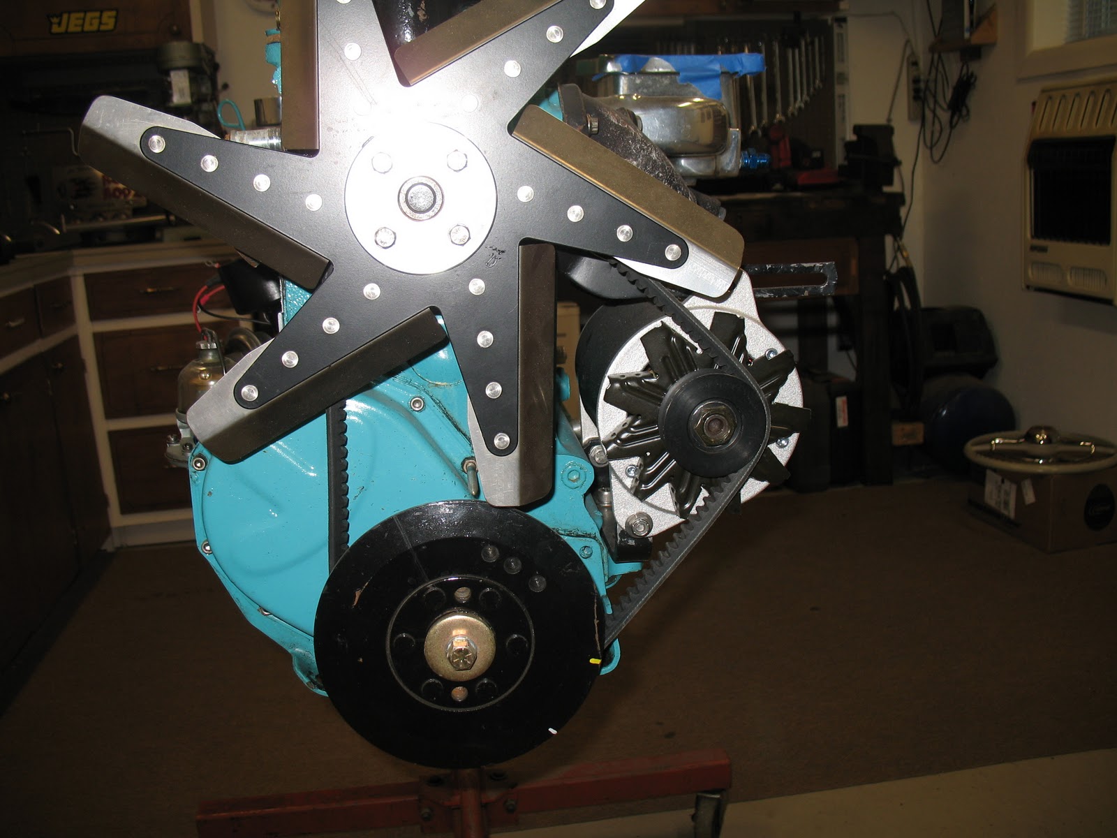
The wheelbase checked out perfect so the next step was installing the engine with bell housing and see how the front mounts would line up. 


It became quickly apparent that different side engine mounts would need to be fabricated as the front mount sits directly over the rack and pinion.  I ordered the universal frame mounts from Chassis Engineering and found several examples/pictures of how other guys had fabricated the mount that bolts to the side of the block.   Before cleaning the frame rails for paint, I needed to remove the stock brake master cylinder from under the driver's floor area.  The clutch and brake pedals pivot off the stock master cylinder so I had also ordered a special bracket that will attach the stock pedals and allow using a new dual master cylinder designed for a Mustang.  Here's the stock configuration.  These pics will help me make sure everything is back together correctly later.


Dan came over last Sat afternoon and we spent the day checking the clearance of the oil pan to the frame with the transmission bolted to the bell housing.  Since the transmission crossmember previously fit tightly under the transmission mount with the engine in place, I wanted to make sure the oil pan would clear the frame with the transmission and crossmember in place.  The pan clears just fine and the timing cover/front mount clears the rack and pinion assembly.  Since the front mount isn't going to be used, I'm seriously considering removing the mount flange from the front plate.  I have an extra one I can modify with a cut off wheel.  After the engine/transmission were removed, we attempted to set the front end assembly back on the frame.  It was immediately apparent that the inner fenders are going to have to be cut in order to clear the top hats that bolt to the top of the Chassis Engineering crossmember.  Until now, I had been able to adhere to my goal of not cutting any part of the car. But there's no getting around this one without having custom inner fenders fabricated and that's not going to happen!  Once I accepted the fact that continuing with the idea of being able to return the car at some point to its restored state wasn't sensible, the conversation turned to other improvements that would require slight modification to the car.  The stock guages became a target for upgrade as well as the speedometer.  Matching the speedo driven gear to make the stock speedo accurate wasn't possible since the gears were no longer available.  So, yesterday I called Dolphin Gauges down in Florida and ordered their 5 gauge electronic package along with the 41 Chevy dash panel.  Everything will bolt in and provide new oil press, water temp, volts, and fuel gauges along with a programmable electronic speedo.  Pics to follow later this week.
     Last Friday, Dick, Dan and I had discussed the details of making a steering column to look like the original.  That too would be a tedious project and I had discovered the wiring in the old turn signal system was just as deteriorated as the rest of the 6 volt wires.  Abandoning the need to keep things looking original at all costs opened the door to consider a custom steering column and a new steering wheel.  A call to Ididit in Tecumseh, Mi., answered my questions on which parts to use and everying was ordered yesterday from Lane Automotive.  And....it was delivered via UPS today!  I ordered a tilt column which is ready for paint.  Lecarra makes a 2 spoke, old looking steering wheel with a chrome horn ring that comes ready for paint too.  I ordered those pieces yesterday. 
     Last Friday nite several of the Road Rodz club members met for some food and talk.  I mentioned my concern over how to replace the wiring that runs above the headliner in the 41 and Phil said he knew of a product to allow the wires to run across the floor and still be protected.  He emailed me the name on Saturday. It is called Gray Stuff from Ron Francis Wiring.  That got ordered yesterday along with the steering wheel from Summit Racing. 
     Yesterday, I also made a trip to the Napa paint store and had some satin black mixed up for the frame parts and some beige to match the old steering wheel and column.  At least I can keep things the same colors!  I finished the day yesterday by removing the rest of the dash parts that won't be used as well as the speedo cable.  The lower kick panels are removable and have plenty of room behind them for speaker installation.  Here's a couple pics of the interior all stripped out and the front of the car with very little left of the stock parts.

I had intended to ship the original radio out to California and have it retrofitted to maintain the front parts while integrating a new am/fm/mp3 input system.  However, with the new direction in mind, I decided to just purchase a retro style radio and speakers from Retro Sound USA.  Got those ordered today along with an adapter plate to allow proper fit in my dashboard. 
     I wire brushed the rust and scraped the crud off the frame yesterday.  Next step is washing it all down with mineral spirits followed by a wipe with lacquer thinner.  Some masking and protective covering on the car and I'll be ready for painting all the black parts.
     My wallet is a bit lighter since this project began but it'll all be worth it when the 41 is back on the show circuit next year.  The wife and I are really looking forward to being able to jump in the 41 any time we have a nice evening and go for a ride without fear of problems with the car.  The modernization direction is not only going to provide a more reliable vehicle but now I can sell off the original parts and recoup some funds.